Cost Reduction
Q Tech Products Insights • Practical Guide
How to Reduce Tooling Cost Per Component in CNC Machining
Practical strategies for moving away from single-source proprietary grooving and turning inserts toward standard ISO geometries while maintaining cycle time and surface finish.
For CNC production machine shops running high-volume automotive and general engineering parts, consumable tooling often represents between 3% and 8% of total manufacturing costs. However, when machining processes rely on proprietary, single-source inserts, this expenditure frequently escalates out of control.
1. The Trap of Single-Source Proprietary Inserts
Many tooling manufacturers design holders that accept only their proprietary insert shapes. While these may perform well during initial machine trials, replacement inserts typically cost 300% to 600% more than standard ISO geometries. Furthermore, lead times of 6 to 10 weeks leave production lines vulnerable to supply disruptions.
2. Transitioning to Standard ISO Insert Economics
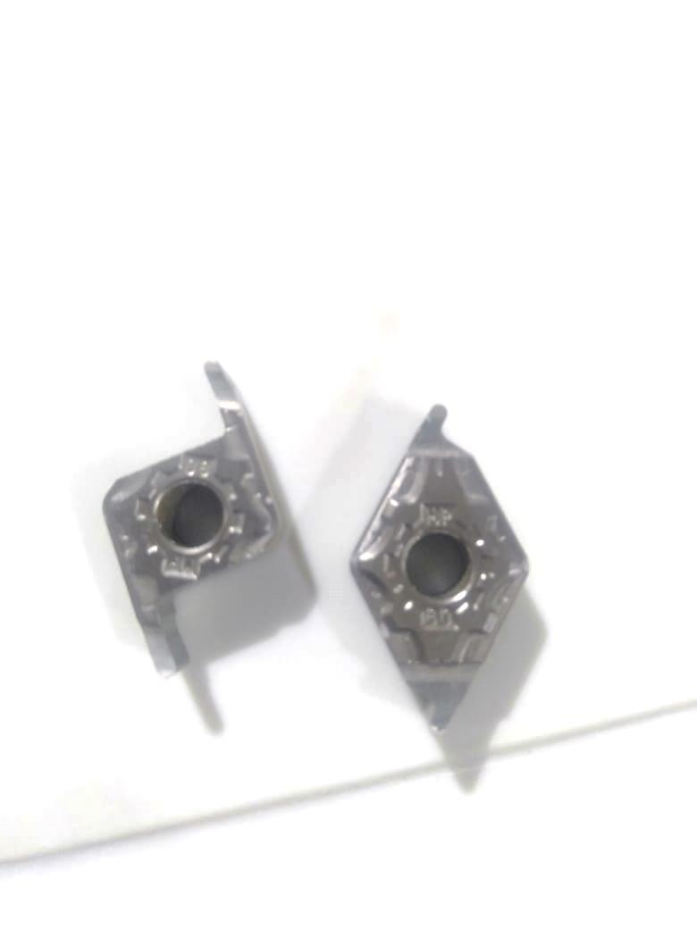
In our documented case study with Sri KVS Industries, oil grooving operations were costing ₹5.00 per component using proprietary grooving inserts. Q Tech re-engineered the toolholder geometry to utilize standard, multi-corner ISO turning inserts. The insert cost plummeted from ₹5.00 down to ₹0.80 per piece—an immediate 85% cost cut saving over ₹2,62,500 annually on a single line.
3. Key Rules for Cost-Reduction Retrofits:
- Evaluate insert corner economics: Prioritize double-sided inserts (e.g. 12-corner negative face milling inserts or 6-corner WNMG turning inserts) over single-sided inserts.
- Ensure rigid pocket seating: The toolholder pocket must feature hardened carbide shim seats to protect the body during edge wear.
- Optimize coolant targeting: Proper high-pressure coolant delivery directly at the tool-chip interface extends carbide life by 40% to 70%.
Precision Boring
Q Tech Products Insights • Practical Guide
Boring Bar Selection for Deep Bore Applications
Practical selection rules for length-to-diameter (L/D) ratios, shank materials, and vibration damping when machining deep bores beyond 4D overhang.
Internal boring is inherently more challenging than external turning because the tool is supported only at one end. In deep bore applications exceeding 4 times the bar diameter (4D overhang), standard steel boring bars encounter severe deflection, vibration, and chatter.
1. Overhang Deflection Challenges in Deep Bores
As overhang length increases, the boring bar rapidly loses dynamic rigidity. This causes dimensional taper from bore entrance to bottom, circularity errors, chatter marks, and accelerated insert cutting edge wear.
2. Overhang Guidelines & Shank Material Selection:
- Up to 4D Overhang: High-tensile alloy steel boring bars (vacuum hardened to HRC 44–48) perform reliably with positive rake inserts.
- 4D to 6D Overhang: Heavy metal (densimet) or solid carbide shanks with high rigidity are recommended to maintain bore concentricity.
- 6D to 8D+ Overhang: Tuned mass damper boring systems or custom vibration-damped tool bodies engineered by Q Tech Products.
Bore Accuracy
Q Tech Products Insights • Practical Guide
Micro Fine Boring: Achieving Tight Bore Tolerances (<13 Microns)
How dial-calibrated micrometer heads, proper insert nose radius selection, and internal through-coolant achieve IT6 bore tolerances and CPK > 1.33.
Achieving bore tolerances below 13 microns (±0.0065 mm) in high-volume production requires eliminating three critical sources of variation: spindle thermal expansion, insert nose deflection, and vernier adjustment inaccuracy.
1. Vernier Micrometer Resolution
Standard roughing or semi-finishing boring bars rely on set-screw clamping, making adjustments finer than 0.02 mm nearly impossible on the machine. Q Tech micro fine boring bars incorporate an internal hardened micrometer screw mechanism with 0.002 mm (2 microns) radial adjustment per dial graduation.
2. Managing Thermal Drift and Coolant Pressure
In deep bores (such as Rane's 70mm steering gear housing bore), cutting temperatures in dry or flood machining cause bore taper from entrance to bottom. High-pressure through-spindle coolant directed through the boring bar body stabilizes thermal equilibrium and flushes long swarf out of the bore immediately.
3. Case Proof: CPK 1.43 at Rane (Madras) Ltd
By pairing a rigid 4th axis VMC setup with Q Tech's custom micro fine boring bar, Rane improved process capability on a 12.99 mm bore from CPK 0.70 to 1.43, meeting the stringent quality criteria for the Deming Prize.
Cycle Time Reduction
Q Tech Products Insights • Practical Guide
Combination Boring Bars: Multiple Operations in One Tool
How consolidating rough boring, semi-finishing, chamfering, and facing into a single multi-insert tool slashed 42% of cycle time on CNC turning centers.
In high-volume CNC manufacturing, machine cycle time is dominated not only by actual cutting feed rates, but by non-cutting idle time: rapid tool retracts, turret indexing, spindle deceleration/acceleration, and approach passes.
1. The Penalty of Multiple Tool Stations
Machining a stepped bore typically involves: (1) Rough boring tool, (2) Finish boring tool, (3) Internal chamfer tool, and (4) Spot-facing tool. Each tool change consumes 4 to 7 seconds. More critically, moving between tool stations introduces cumulative concentricity runout caused by turret repeatability tolerances.
2. The Combination Tooling Solution
Q Tech Products designs multi-pocket combination boring bars where roughing inserts, finishing cartridges, chamfering inserts, and facing cutters are positioned along a single hardened tool body at precise axial and radial offsets.
3. Rane (Madras) Steering Housing Benchmark:
Q Tech consolidated 7 cutting operations (3 stepped bore diameters, 3 internal chamfer angles, and 1 shoulder facing cut) into a single tool pass. The result was a 42% reduction in total machining cycle time and guaranteed radial runout < 0.008 mm between all bore diameters.
Import Substitution
Q Tech Products Insights • Practical Guide
Import Substitution in CNC Cutting Tools: Maintaining Quality While Slashing Lead Times
How Indian automotive and defense manufacturers substitute expensive European and Japanese milling cutters with domestic precision tooling.
For decades, Indian OEMs assumed that high-precision indexable milling cutters and fine boring systems could only be sourced from European or Japanese suppliers. However, overseas procurement brings major liabilities: 8-to-12-week delivery lead times, premium pricing driven by import duties, and zero local engineering customization.
1. The Modular Cartridge Revolution
At Brakes India Limited, imported MNC half side & face milling cutters were frequently scrapped because an insert pocket chipped during heavy caliper slotting. Because the cutter bodies were single-piece construction, one damaged pocket ruined the entire expensive tool.
2. Domestic Engineering Superiority
Q Tech designed a modular replacement cutter featuring replaceable cartridge pockets. If a pocket sustained damage, only the ₹800 cartridge was replaced rather than the ₹45,000 cutter body. Tool life and dimensional stability matched the European benchmark over 3+ months of continuous production.
Process Optimization
Q Tech Products Insights • Practical Guide
How Custom Tooling Can Reduce Machining Cycle Time & Machine Setups
Analyzing the trade-off between standard catalog tooling and custom-engineered cutting tools in high-volume production lines.
When is it economically justified to invest in custom tooling rather than buying off-the-shelf catalog tools? The answer lies in annual production batch volume and machine bottleneck analysis.
1. The Cost of Second Setups
In our work with Srimukha Precision Products, electric motor rotors required machining on both front and rear faces. The standard process required transferring parts to a second CNC lathe for rear shoulder machining. This second setup required manual handling, introduced intermediate inventory queues, and caused concentricity runout.
2. Single-Setting Back-Turning
Q Tech engineered a custom under-shoulder back-turning tool that reached behind the rotor core during the primary chuck setup. Front turning, OD skimming, and rear facing were completed in one continuous cycle. This eliminated the second machine setup completely, freeing up a complete CNC lathe and halving component handling time.
Milling Dynamics
Q Tech Products Insights • Practical Guide
Face Milling vs Side & Face Milling: Application Considerations
Comparing machining applications, chip evacuation, tool setup, and insert geometry selection between face mills and disc slotting cutters.
Selecting between face milling cutters and side & face disc cutters requires evaluating component rigidity, clamping orientation, and metal removal volume.
1. Face Milling Dynamics
Face mills cut primarily on their face and periphery, with cutting forces directed axially into the machine spindle (especially with 45° lead angles). This configuration provides maximum stability for large planar surfacing on cast iron cylinder blocks and pump bases.
2. Side & Face Milling Dynamics
Side & face cutters machine deep slots with three cutting edges simultaneously (both sides and periphery). Chip evacuation in deep slots is critical; if chips pack into the gullet, cutter teeth will fracture. Q Tech side & face cutters utilize staggered teeth geometry—alternating left and right cutting edges—to balance axial cutting forces and prevent cutter wedging in deep slots.
Toolholder Design
Q Tech Products Insights • Practical Guide
When Should You Use a Custom Tool Holder Instead of Standard ISO Tooling?
Five critical manufacturing scenarios where catalog tool holders cause chatter, clearance collisions, or excessive insert wear.
Standard ISO 5610 tool holders are designed for general-purpose turning in open geometries. However, in automotive and defense components, tool clearance is rarely wide open.
Five Indicators You Need a Custom Tool Holder:
- Severe Clearance Limits: When component shoulders, chuck jaws, or tailstocks leave less than 3 mm clearance for a standard 25x25 shank.
- Compound Multi-Directional Turning: When an operation requires turning, under-facing, and chamfering without indexing the turret.
- Vibration and Chatter: When overhang requires custom reinforced cross-sections or vibration-damped alloy bodies.
- Special Insert Geometry Adaptations: Converting proprietary grooving pockets to standard ISO turning pockets to slash insert costs.
- Through-Tool Micro-Coolant: Standard holders lack directed coolant nozzles aimed at the precise shear zone in high-temp alloys.
Approachability
Q Tech Products Insights • Practical Guide
How Tool Approachability Affects CNC Machining in Intricate Components
Overcoming tool interference, collision hazards, and cantilever deflection when machining deep internal pockets and recesses.
Approachability constraints occur when the physical envelope of the toolholder, clamp wedge, or machine turret interferes with component walls before the insert cutting edge reaches the target surface.
1. The TVS Motor Company Transmission Case
At TVS Motor Company, machining an internal snap-ring retaining groove inside a narrow cavity presented severe interference issues. Standard boring bars collided with cast internal ribs, while grinding down a standard tool ruined its cross-sectional rigidity, causing chatter.
2. Low-Profile Cartridge Engineering
Q Tech Products designed a custom low-profile grooving cartridge with an asymmetric tool shank. The cartridge maintained rigid full-length insert support while providing 0.8 mm clearance against the component ribs. Groove width tolerances (±0.02 mm) and cycle time targets were met on the very first tryout.
Tooling Economy
Q Tech Products Insights • Practical Guide
Reducing CNC Tooling Cost Without Sacrificing Tool Life & Productivity
A comprehensive checklist for engineering managers and purchase heads to audit cutting tool spend and improve edge life.
Cost reduction in manufacturing often fails when procurement departments simply purchase cheaper, low-quality cutting inserts. Cheaper inserts wear faster, force frequent machine stops for insert indexing, and degrade surface finish—ultimately increasing cost per finished component.
True Tooling Economy Checklist:
- Increase Usable Cutting Edges: Switch from single-sided positive inserts to double-sided negative geometries (e.g. 12-corner face milling inserts or 8-corner CNMG turning inserts).
- Adopt Modular Cutter Bodies: Invest in cutter bodies with replaceable cartridge pockets to avoid scrapping expensive toolholders during unexpected shock loads.
- Eliminate Non-Cutting Cycle Time: Use combination boring and chamfering tools to free turret stations and cut spindle cycle time by 30% to 50%.
- Optimize Tool Overhang: Use rigid, split reduction sleeves instead of set-screws to eliminate boring bar runout and double insert edge life.
- Direct Engineering Partnership: Work directly with tooling manufacturers who provide on-machine tryouts and CPK validation rather than catalog traders.